views
Starting with Safety and Understanding
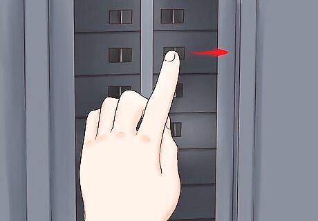
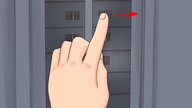
Turn off electric power. Turn on the light or device being controlled by the 3-way switches, if you already have them installed. Locate the circuit breaker box. Identify the circuit breaker that controls electricity in the area where you will be working. Turn off that circuit breaker.
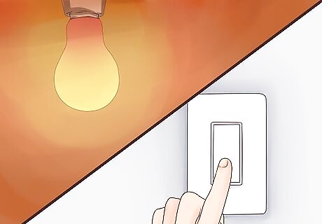
Return to location you plan to wire to verify that there is no electric flow to that device. If the device is still lit up or working, the wrong breaker was opened. You may also use a current/voltage detector, to be on the safe side. (Safety Note: Be sure to test it on the live wires before you use it to confirm they are no longer live.) If it lights up, you did not identify the correct circuit breaker and need to return to the circuit breaker box and start over. If it does not light up, there is no voltage, and it is safe to proceed There are also inexpensive "search" devices that plug into a receptacle and generates a signal that can be detected at a specific circuit breaker, using the matching detector. When the correct breaker is off, the signal stops.
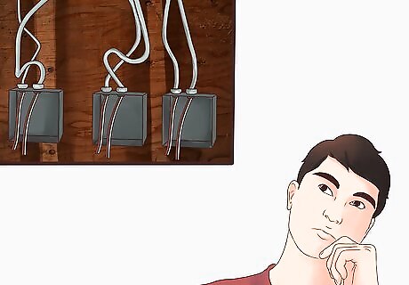
Study the 4-way switch and the manufacturer's directions. A 4-way switch has 4 terminals or poles. Two terminal/poles are labeled "in," and two are labeled "out." Pairs of wires, called "travelers," will connect to each side. When the switch is operated, current will either travel straight through or crisscross. Whether "on" is up or down is determined by the positions of the other switches at that moment. A third conductor passing through the junction box with the 4-way switch, will not be connected to the 4-way switch. It is used for carrying the power from the far-end of the final 3-way switch back to the light/device being switched. There will also be a "grounding" terminal on the switch, which is connected to the bare grounding wires (or to a metallic junction box, if you have one) for additional safety.
Identify the travelers. Two 3-way switches are connected to each other via "traveler" wires, only one of which is "hot" in any given switch setting combination. The 4-way switch connects in the "middle" of the two travelers. Each 3-way switch has a "common" terminal and two traveler terminals. Find the wires connected to the two traveler terminals. Some electricians use colors to identify travelers, because white may only be used for a neutral, unless it has been properly identified with another color (e.g., black, red, blue, yellow -- but NOT green). If you find travelers using white wires, use colored tape to mark each one in each junction box or device box where you find it, so that it will not be incorrectly viewed as a neutral wire. Which wires are the travelers may vary if the 3-way switches are connected to each other by way of wiring within the fixture ("fixture between") or if they are connected directly to each other and then to a fixture (known as "fixture beyond"). Note that a branch circuit may "supply" either the fixture or any of the switches and you must first determine which junction/device box is the source for the power to be switched as well as whether the fixture is between the switches or at one end or the other. This article describes the configuration for feeding the fixture with power and having the 3-way and 4-way switches lined up beyond the fixture. The attached video shows a configuration in which power is fed to one 3-way switch, through the other switches, and finally to the light at the far end. The electrical theory is the same, although the selection of colors for the travelers and the switched "hot" is different. If a neutral wire is required at each switch location, a different configuration will be required, as shown in the video.
Wiring the Fixture
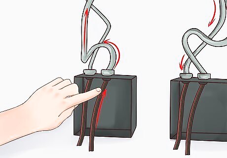
Look at the wires involved. In this article, we consider the box having the lighting fixture or device as the "source" of the power from the circuit breaker. Two wires enter the source fixture's wire box from the circuit breaker; the black one is called "line" or "hot", and the white wire is neutral (which is grounded at the breaker box). Only the black/line/hot wire is going to be switched. The white/neutral connects directly to the light/device. Note that some jurisdictions now require a neutral wire at each switch location, due to modern changes in switching technology that may require a neutral for a complete circuit, such as "smart switches". For simplicity, this article ignores such a requirement, as these "extra" neutral wires are simply run to each location and are not being switched.
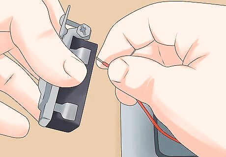
Connect the black wire coming from the breaker into the fixture location to the black wire going to the first 3-way switch. This is the "supply" to the switching system. Remove about 0.25 inches (0.635 cm) of rubber/plastic insulation from each wire. Use pliers to twist the exposed ends of the two black wires together. Complete the connection by screwing a properly sized wire nut onto the joint tightly. Lightly tug on each wire to make sure they are both tightly connected. Wrap the wire nut connection with electrical tape for safety and durability. Repeat this wire connection process at each wire connection. Do not nick or skin the wires anywhere other than at the ends being connected.
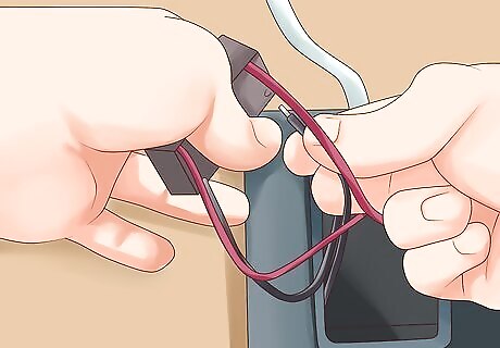
Connect the white wire coming into the fixture/device box to the white wire on the fixture.
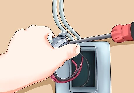
Connect the black wire coming from the fixture to a red or white wire that leads out of the box to the first 3-way switch box, and (if using white) identify the white wire with a color marking, such as red electrical tape. This red wire is the one that will supply power to the light after traveling through all of the switches. It is the installer's choice whether to use the red wire or "white" wire (identified with blue or other color) as a traveler. This description uses the red wire as the "switched" wire from the furthest switch. The video uses a different technique to "carry" the white wire, as neutral, through each junction box, all the way to the remote light.
Wiring the First 3-Way Switch
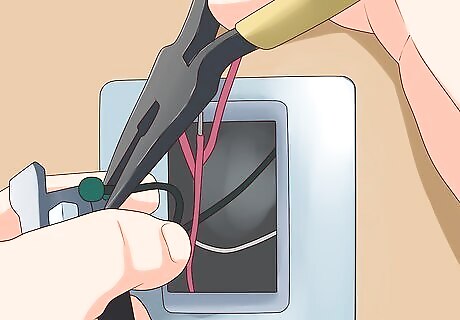
Connect the black wire coming into the switch box to the "common" terminal on the first 3-way switch. Note that this black wire will always be "hot", regardless of the switch settings. Remove about 0.25 inches (0.635 cm) of rubber/plastic insulation. Use needle-nosed pliers to form a loop in the stripped wire. Complete the connection by wrapping the loop 3/4 of the way around the screw terminal and tightening the screw to hold the loop flat against the terminal. Do not overlap the wire with itself beneath the screw terminal. Repeat this wire connection process at each switch connection. If the switches have "back-wiring slots", as well as screw terminals, avoid using the back-wiring because it may be less reliable in the long run than the screw terminals.
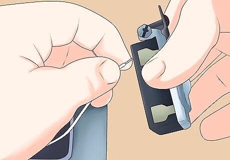
Attach the red (or red-identified white) wire coming into the switch box to the red wire going to the next switch box, and eventually all the way to the final 3-way switch.
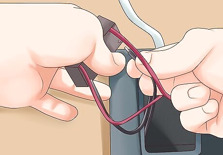
Attach the black wire and white (marked with blue) wire going out of the box to the next switch to the bottom poles of the 3-way switch. These two wires are the "travelers" to the 4-way switch. The third wire (the red) will not be switched at the 4-way location, but passes to the final 3-way switch. Note that a 3-conductor cable is often used for connecting 3-way and 4-way switches to each other, containing black, white and red conductors. The white conductors should be marked to identify their function as travelers (e.g., the white with a blue tape marking). Other installers prefer to use two-wire cables from each switch to the next, purely for the travelers, and to run the hot or switched hot a different route to and from the fixture. Some 3-way switches may have the "common" terminal on one side and the two "travelers" on the opposite side. Just make sure your black "hot" wire goes to the "common" terminal.
Wiring the 4-Way Switch
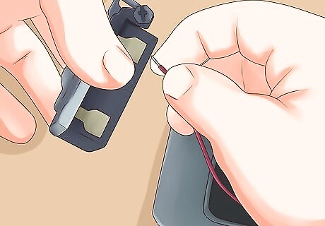
Attach the red wire entering the 4-way switch box from the first 3-way switch box to the red wire going to the next 4-way switch.
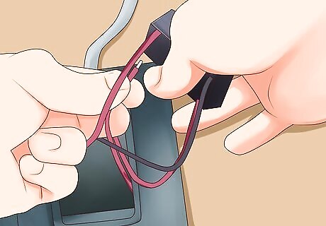
Attach the black and white/blue traveler wires entering the 4-way switch box to the "in" terminals, often the top terminals on the 4-way switch - black on the left top pole and white/blue on the right top pole. Some 4-way switches may have the "in" and "out" pairs opposite each other, rather than top and bottom. Look at the markings on yours and read the instructions carefully.
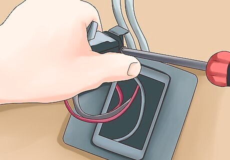
Attach the black and white/blue traveler wires exiting the 4-way switch box to the next 4-way (or final 3-way) switch box to the "out" terminals, often the bottom terminals on the 4-way switch - black on the left bottom pole and white/blue on the right bottom pole. If you are adding more 4-way switches, repeat these steps with the two 3-conductor cables entering each 4-way switch location from the adjacent switches.
Wiring the Last 3-Way Switch
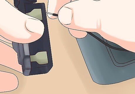
Attach the red wire entering last 3-way switch box to the common ("com") pole of the 3-way switch.
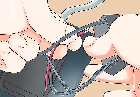
Attach the black and white/blue wires entering the box to the light colored poles at the bottom of the switch - black to the bottom left pole and white/blue to the bottom right pole. Not all 3-way switches are designed the same way. Just make sure the traveler wires are not connected to the common pole of the switch.
Completing the Circuit
Perform final assembly of the switches and wiring into their boxes. Many electricians use electrical tape to make a final wrap or two around each switch to cover the screw terminals prior to installing the switches into their boxes. This is intended to reduce the risk of accidentally shorting things to the terminals. Double-check that all connections are proper before carefully packing the wiring and switches back into each switch box. Screw the switches into their boxes, being careful not to nick or pinch any wires.
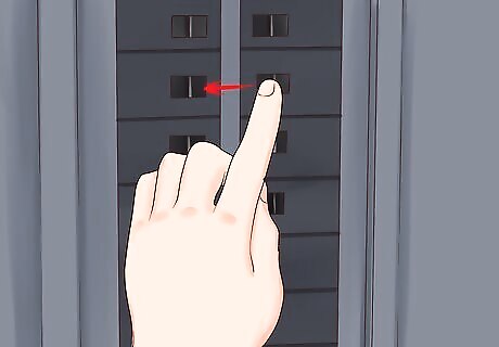
Restore electricity by turning circuit breaker back on.
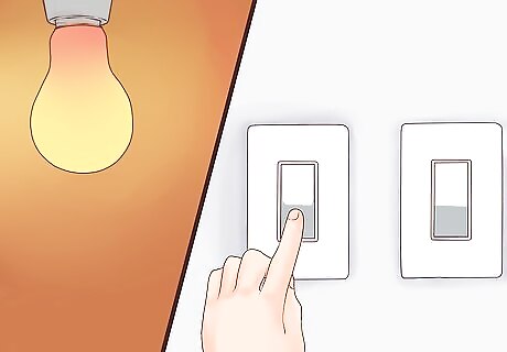
Test all of the switches. Turn the light/device on and off with one switch, then off and on with the next, then off and on with the last. If changing any switch (up or down) does not turn the light/device on or off, regardless of the settings of the others, turn off the breaker and re-check your wiring. There are 8 possible combinations, when using three switches (on and off). They should all function properly.


Comments
0 comment