views

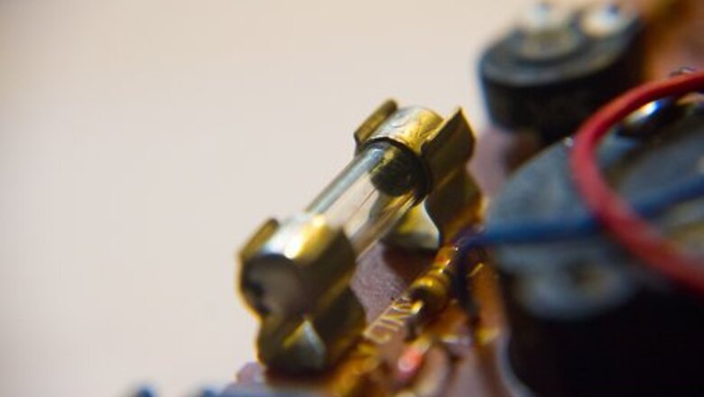
Determine that a fuse has opened (blown) by inspecting the metal link through the glass. You may have to open a door, but you do not need to remove covers.

Figure out what kind of fuse needs replaced. For the screw-in type glass and type "S" tamperproof fuses: If unable to visually inspect the metal link, use of a voltmeter, wiggy or neon test light should resolve the problem by following the steps below (they may also be checked via continuity test light, this procedure is detailed further below). While holding one probe or lead of the test equipment (meter, wiggy or light) to an unpainted exterior metal part of the fusebox, touch the other probe to the metal thread of the fuse holder / fuse. This is done by pushing the probe along the outside rim of the fuse until it contacts the aluminum or copper metal in to which the fuse screws in. If you get an indication of power (120 volts indication or lamp) this is not the fuse that has opened. Continue checking the rest of the fuses by removing the probe from the the fuse tested, and repeating the procedure for the next fuse. A fuse that does not test to 120 volts or does not fully illuminate the lamp, is a likely candidate for replacement (meters are always preferred over test lamps as a lamp may not provide enough of a change in brilliance that can be detected by eye). Remove the fuse in doubt by turning it counter-clockwise. If the fuse has ceramic or plastic threads and two small copper contacts under the head of the fuse, they are type "S" tamper-proof fuses. These fuses are a two piece protection system consisting of a threaded insert that is installed into the fusebox (like a regular glass fuse) and the the fuse itself that is installed into the insert. The fuses and inserts have different threads for the different values of fuses. The threads are such that they prevent installing a fuse with a value other than intended to protect the circuit (it is impossible to to put any fuse other than a 15 amp type "S" tamperproof fuse in a 15 amp insert, etc). The type "S" tamperproof fuse system removes the guesswork and danger of installing the wrong value fuses. The standard glass fuses, like the type "S" tamper-proof counterparts, are available in 15, 20 and 30 amps values. There are also 10 and 25 amp, but are not very common. To properly select glass replacement fuses, the cover of the fusebox should be removed. The 15 amp fuse is to protect #14 gauge copper wire, 20 amp fuse protect #12 copper wire, and 30 amp for #10 copper wire. These are the most common wire sizes in the fuse box. The #14 is the smallest wire connected to a glass fuse and the #10 is the largest wire connected to a glass fuse. There will probably only be (2) #10 wires, (4) #12 wires and the rest #14 wires. The #14 are used for general lighting and plugs throughout your house - except for those plugs in the kitchen, dining room, clothes washer & dryer. The #12 are for plugs in the kitchen, dining room, clothes washer and specialty or dedicated appliances such as larger room air conditioners, etc.. #10 may be used to feed an electric clothes dryer, electric water heater or another small panel elsewhere - garage, etc. These are estimates - all panels and homes differ, and this should only be considered a starting point. You will see larger wires connected to the MAIN and RANGE fuse holders, and possibly wires that connect to 2 terminals at the bottom of the fuse block. These are usually used for an electric water heater or small panel elsewhere. Don't worry if you don't see these wires. For the cartridge fuse types: Generally, cartridge fuses do not have any visual indicator when they open. They must be checked with a voltmeter "in circuit" or with an ohm meter or continuity tester "out of circuit". Many old fuse boxes provide for MAIN and RANGE fuse holders. The MAIN is designed for (2) 60 amp 250 volt fuses, and the range is designed for (2) 40 amp 250 volt fuses. With the fuses and the holders still in the fusebox, touch one probe to an unpainted metal surface of the fusebox. Locate the four small holes on the fuse holder, and press the other probe into the hole until it stops. Check for power indication. Repeat procedure for remaining 3 holes for this fuse holder. The holes align with the metal caps of the fuses, and should indicate power present at ALL four holes. Any hole without a power indication corresponds to an open fuse directly behind the hole under test. Check the orientation of the fuse holder by looking for the ON and / or OFF indicators in the middle of the short sides of the fuse holder. Remove the fuse holder by firmly pulling it straight out. Remove the fuse in question and replace it with a maximum of a 40 amp fuse for the RANGE fuse holder or 60 amps for the MAIN fuse holder. You must use fuses rated for 250 volts. Return the fuse holder to the fusebox observing the orientation of the holder (if you get it wrong, simply remove it, rotate the holder 180 degrees and reinsert).

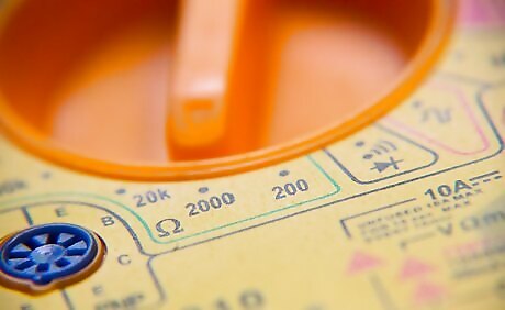
As mentioned above, another method to check fuses requires a continuity tester or ohm meter. A continuity tester is similar to a test light, but that this light has its own power source (battery) as part of the tester. It must never be connected to another power source - the way a neon test light would. Regardless of the method used (ohm meter or continuity tester), the procedure is the same, after preparing the tool for use. Continuity Test Light and Ohm Meter Method Set the ohm meter to Ohms (R x 1 or R x 10 scale) / Turn the continuity tester on. Put the meter probes onto the "Common" and "Ohms" jacks on the meter. Touch the opposite ends of the probes to each other. The meter should move to zero or close to it. Find the thumb wheel on the meter marked Ohms Adjust or Zero Adjust. Move the wheel to make the needle of the meter align with 0. The continuity light is checked by touching its probes together. The light on it should illuminate. Remove the fuse to test from the panel completely. All fuses must have a way for electricity to enter and exit. Cartridge fuses have these points at the ends of their body. They may be tested without removing them from the fuse holder. Placing the fuse or fuse in the fuse holder on a non-conductive surface, and touch a probe to each end. A zero reading on the meter or light on the continuity tester indicates a good fuse. Glass fuses have these points located at the center of the bottom of the fuse and the threaded sides (just like a light bulb). Touch the probes to these points to test the fuse. Again, we're looking for a zero reading or the continuity light to illuminate. Lastly, the type "S" tamperproof fuse points are the center bottom (like the glass fuses) and any copper contact point(s) on the underside of the top of the fuse.


Comments
0 comment